Mind the gap! What to fill and what to leave
01 May 2014, Prove Your Know How, Technical
For builders, particularly those overseeing an entire build, it’s important to ensure sub-contractors (such as painters) don’t accidentally reduce or fill a gap that’s been intentionally left open.
While most gaps in a building need to be sealed to prevent draughts and induction of moisture, spaces are sometimes required to provide separation between materials or elements and to allow drainage and drying, such as behind wall claddings. Understanding the difference is essential to the integrity of the building.
Specifically designed gaps
Specifically designed gaps or openings are incorporated into the building design, so that drainage and ventilation can occur.
“The most important gap requiring sealing is the one between the window or door reveal and the wall framing
Drainage is needed to deal with any water that may have entered the internal wall space through a cladding joint, a change in cladding material or around a window or door opening, so that it can drain out again.
Ventilation is needed to dry any moisture from behind a cladding after the water has drained out, or allow air pressure moderation between the drainage cavity and/or framing cavity and the outside. Pressure moderation restricts air and moisture flow from areas of higher pressure (outside) to areas of lower pressure (inside). This may take place across wall claddings and around window and door openings.
Some gaps must stay open
Examples of specifically designed gaps in E2/AS1 that must remain open include:
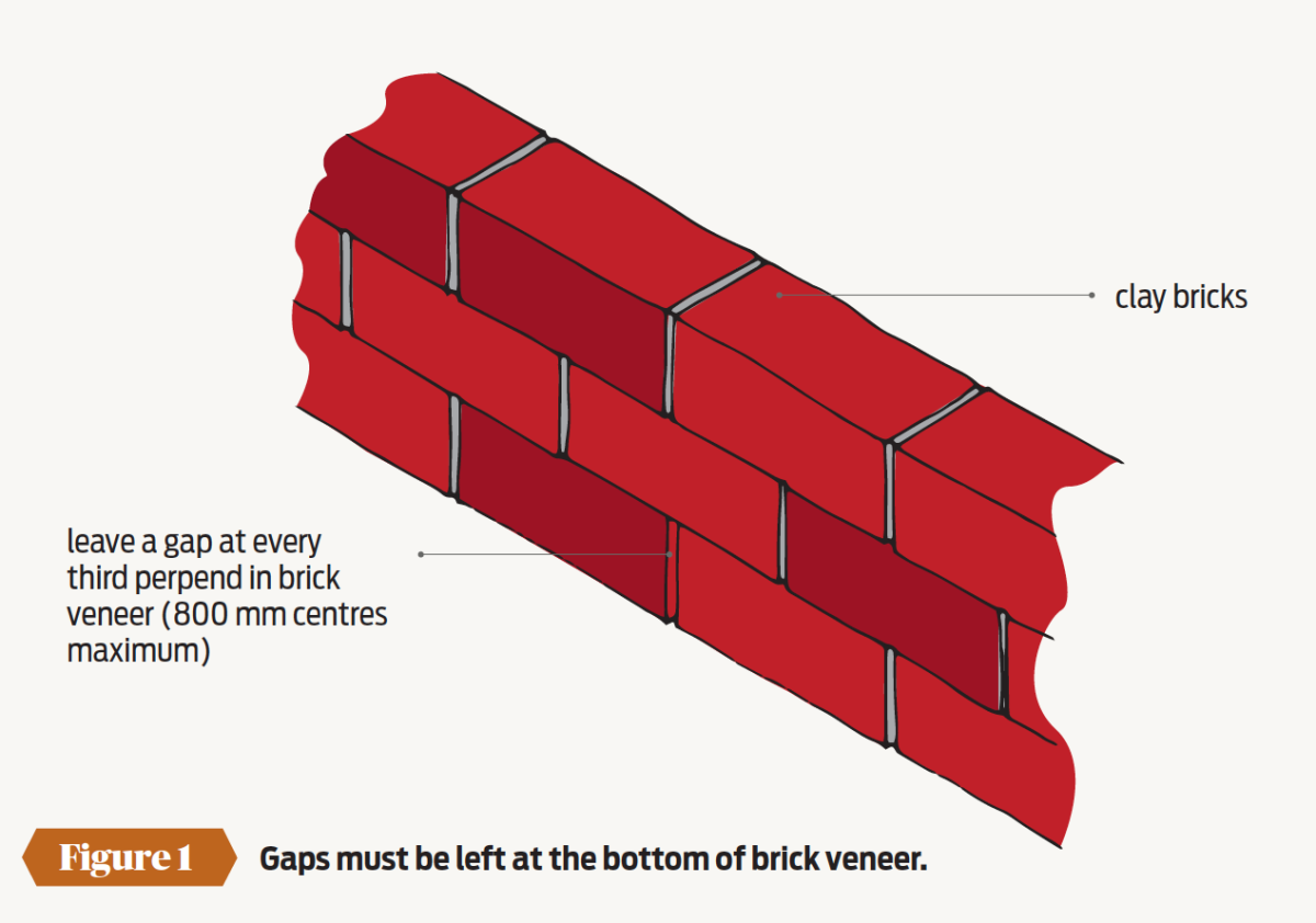
- The drainage slots at the bottom of brick veneer walls at 800 mm centres maximum, ie every third perpend should be left open to allow for drainage (see figure 1).
- Openings at the top of brick veneer walls for ventilation behind the veneer.
- Between the bottom of the cladding and the top of a window head flashing – 5 mm minimum.
- Between the bottom of the cladding and an inter-storey flashing – 5 mm minimum.
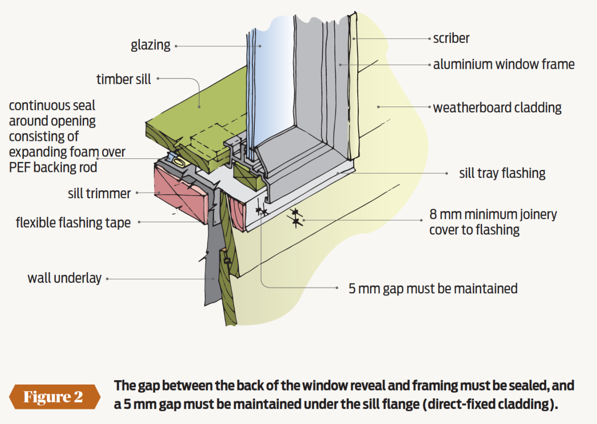
- The sill window flange and the sill flashing for windows installed with direct-fixed cladding – 5 mm minimum.
- A notched apron flashing downturn and the roofing profile – 5 mm maximum.
Another gap that must stay open is an air gap between a flexible roof underlay and roof insulation, so moisture cannot transfer across the materials – 25 mm minimum.
“Specifically designed gaps or openings are incorporated into the building design so that drainage and ventilation can occur
While not a gap as such, ventilation openings must be provided and left clear under a suspended timber floor. NZS 3604:2011 Timber-framed buildings requires 3,500 mm² of clear opening for each 1.0 m² of floor area.
Some gaps must be sealed
In some situations, gaps between elements must not be left open.
The most important gap requiring sealing is the one between the window or door reveal and the wall framing forming the rough opening. A continuous airseal consisting of expanding foam over a PEF backing rod must be installed to prevent air movement from the outside to the building interior (see Figure 2).
- Other gaps that must be sealed include
- Movement control joints in claddings.
- Movement control joints in tile finishes.
- The space between the back of the jamb flange and window cladding of windows that are installed with direct-fixed sheet claddings.
These joints must be sealed with a flexible sealant installed according to the manufacturer’s instructions.
| E2/AS1 | Locaton | Size |
| E2/AS1 | Brick veneer cavity | 40 mm (minimum) to 75 mm (maximum), BRANZ recommends 50 mm |
| E2/AS1 | Top of brick veneer and soffit or cantilevered floor framing above | 5 mm minimum |
| E2/AS1 | Cladding base to apron flashingor membrane deck | 35 mm minimum |
| E2/AS1 | Flashing at top of cladding or inter-storey flashing | 5 mm |
| E2/AS1 | Drained and vented cavity | 18–25 mm (20 mm nominal) |
| E2/AS1 | Expansion gap to vertical flashings with horizontally fixed profiled metal cladding | 5 mm, BRANZ recommends 10 mm |
| NZS 3604:2011 | Rear of bottom edge of direct-fixed cladding and foundation wall | 6 mm |

Register to earn LBP Points Sign in