Building stronger sill skills
07 Oct 2014, Featured, Prove Your Know How, Technical
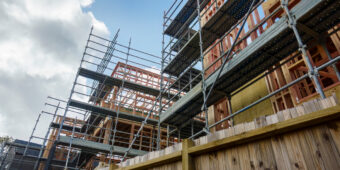
Large, double-glazed windows need proper support, particularly when installed beyond the face of the wall framing. Here are some simple tips to help you get it right, the first time
Two challenges created by large, double-glazed units installed beyond the face of the wall framing are:
- Ensuring the weight of the window is carried down through supporting elements to the building structure.
- Providing support to the sill flashing in direct-fixed cladding situations.
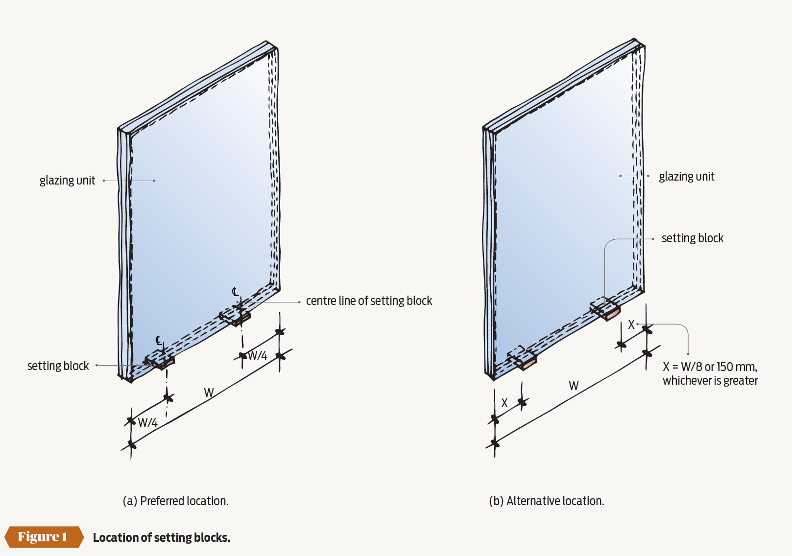
Align setting blocks and frame support blocks
Double-glazed units are supported within the window frame on setting blocks to prevent glass-to-frame contact. They are used in pairs and must be located in accordance with AS/NZS 4666:2012 Insulating glass units, generally at ¼ and ¾ points across the width of the glazing units (see Figure 1a). They may also be located within either ⅛ of the width, or 150 mm from, the glass edge (see Figure 1b).
For direct-fixed claddings, E2/AS1 requires aluminium window frames to be supported on frame support blocks. These may either be fitted to the frame by the manufacturer or be a proprietary product that is installed by the window installer. However, E2/AS1 does not state where the support blocks must be positioned.
Support blocks must be located directly underneath the setting blocks, to ensure the load of the windows is transferred directly to the building structure. In some situations, windows have failed because the support blocks have not been aligned with the setting blocks.
Therefore, before installing the window, confirm the location of the setting blocks and ensure that the support blocks align with them (see Figure 2).
Sill flashing support for windows
The flat sill tray flashing that is required by E2/AS1 for direct-fixed claddings must also be supported and allow for the installation and support of the frame support blocks.
Typically, the sill tray is supported at least in part by the sill trimmer (E2/AS1 Figure 72A)and by the top edge of the cladding, where it is accurately trimmed to the opening (E2/AS1 Figures 81 to 84 for weatherboards and Figure 115 for flat sheet cladding).
A problem can arise where the cladding is not installed accurately and there may be insufficient bearing for the frame support blocks, because of the cladding used and/or the location of the installed window frame; for example, E2/AS1 Figure 90 for fibre-cement weatherboards.
Where this occurs, the options are to install:
- A metal angle bracket to the sill trimmer (not a proprietary sill support bar used for cavity construction) to support both the part of the sill tray flashing forward of the framing and the frame support blocks (see Figure 2).
- A horizontal metal flat sealed to the sill tray and screwed with a sealed fixing into the upper face of the sill trimmer and projecting forward of the framing line, on which a frame support block can be placed (see Figure 3).
Figure 4 shows the board and batten cladding trimmed to the line of the sill trimmer, with support also provided by the horizontal batten fixed between the vertical battens. Fixing the horizontal batten between the verticals ensures the vertical board joint is fully protected from the weather – if the horizontal board under the sill is continuous and the verticals butted to it, the bottom edge should be undercut or the flashing downturn extended to provide better weathering to the joint.
Simpler over a cavity
It is worth noting that installing windows is considered easier where a cladding is installed over a cavity; a proprietary sill support bar can be used in this situation and the sill tray flashing omitted.


Register to earn LBP Points Sign in