Get on deck with code compliance
04 Oct 2013, Prove Your Know How, Technical
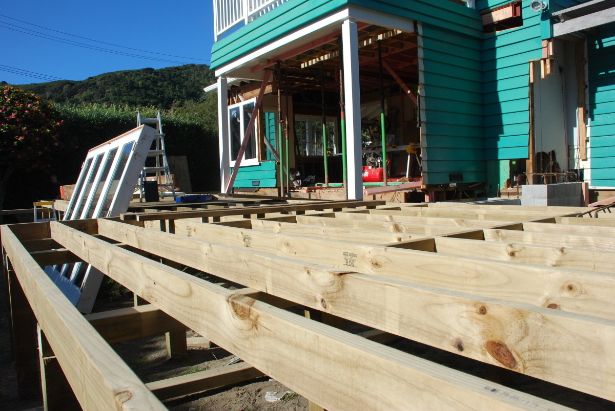
Where it’s possible to fall 1m or more from a deck, the building code requires a barrier that’s able to withstand all imposed, wind and impact loads. In this month’s issue of Under Construction, we look at some options.
In 2012, the Department of Building and Housing (now the Ministry of Business, Innovation and Employment) published Guidance on Barrier Design, which gives guidance and recommendations on designing and installing code-compliant barriers.
As of December 2012, a timber barrier complying with paragraph 4.2.7 of the Guidance on barrier design meets the Building Code clause F4 and B2 requirements. Other barriers will need specific engineering design.
Barrier elements
Barriers for residential decks must:
- Be continuous where the fall height is over 1 m.
- Be at least 1 m high.
- Have openings that prevent a 100 mm diameter sphere passing through.
- Have less than 15 mm gaps between horizontal rails.
- Have the top of the barrier at least 760 mm above a fixed seat.
- Have no sharp edges or projections.
Durability
The components of a barrier are shown in Figure 1. Generally, barrier structural components must have not less than 50-year durability, while other components may have not less than 15-year durability (see Figure 2).
However, if barriers and fixings can be accessed and replaced without difficulty and any failure detected, then the durability may be not less than 15 years. Likewise, baluster infill components that are difficult to access may require 50-year durability.
Design loads of barriers
Barriers must be designed to withstand live (imposed) loads, wind loads and deflection limits from AS/NZS 1170 Structural design actions.
Live (imposed) and wind loads:
AS/NZS 1170.1 paragraph 3.6 and Table 3.3 and modifications in B1/VM1 paragraph 2.2.7 set out requirements for barrier members and connections for residential decks. The loadings described in AS/NZS 1170.1 Table 3.3 include line (top edge), infill (distributed) and concentrated loads.
AS/NZS 1170.2 sets out the wind loads that barriers must be designed to resist.
Deflection limits:
It is recommended that deflection limits do not exceed 30 mm under wind and barrier loads, as described in B1/VM1.
Barrier materials
Barrier materials for timber decks include:
- Timber.
- Glass.
- Metals – aluminium, mild steel and stainless steel.
Timber barriers
Select timber species and grades for residential deck barriers in accordance with NZS 3603 Timber structures standard. The timber grade must be at least SG8 (wet in service), except infill members, which may be SG6 (wet in service).
For durability and treatment, see NZS 3602 Timber and wood-based products for use in building. Pinus radiata must be treated to H3.2. Select metal fixings in accordance with NZS 3604:2011 section 4.4 to have the same durability as the components they connect.
The supporting structure – edge, boundary and deck joists – must be in accordance with NZS 3604 section 7.4 (see Figure 3) and the Adjustments to the deck details in NZS 3604 described in Codewords 54, published December 2012 by MBIE.
Guidance on barrier design includes recommended sizes for timber components (see Figure 2 and Table 1).
Glass barriers
Glass for structural barriers must be Grade A toughened safety glass, complying with NZS 4223.3:1999 Glazing in buildings Part 3: Appendix 3A. Infill glass can also be Grade A laminated.
There are a variety of support systems for structural glass barriers (see Figure 4) and glass infill barriers (see Figure 5).
Guidance on barrier design includes tables from the Glass Association of New Zealand for both structural and infill glass design.
Aluminium barriers
Aluminium barriers must be designed in accordance with AS/NZS 1664.1 Aluminium structures or tested to comply with AS/NZS 1170.0 Appendix B.
Aluminium can have either an anodised or a powder-coated finish. Anodising involves treatment to provide an oxide film over the surface. For an anodised finish, Guidance on barrier design recommends anodising thicknesses of:
- 12 microns for sheltered, non-coastal regions.
- 20 microns for exposed, inland regions (minimum thickness recommended for balustrades and barriers).
- 24 microns for coastal and geothermal regions.
Powder-coated finishes are heat-applied, electrostatically charged paint pigments that fuse to the metal to give a durable and corrosion-resistant coating.
Steel barriers
Steel barriers must be in accordance with AS/NZS 3404 Steel structures standard or tested to comply with AS/NZS 1170.0 Appendix B.
Mild steel has poor corrosion resistance and requires an applied corrosion protection – guidance is given in NZS 3404.1:2009 Section 5.
Stainless steel:
Stainless steel barriers must be either grade 304, for use in non-corrosive environments, or grade 316 for use in corrosive environments.
Finishes include:
- Mill finish – satin.
- Brushed finish – directional grain finish.
- Bright finish – mirror or polished.
- Wire infill for barriers
Wire mesh or rope is frequently used for the baluster infill, as it doesn’t restrict the view. Wire infills are usually fixed to a stainless steel structure (main posts and rails), although aluminium or stainless steel may also be used. Timber is not recommended, as it’s likely to creep, causing wires to loosen off.
Wires should be multi-stranded grade 316 stainless steel in all situations, although grade 304 is allowed in sheltered situations. They may be arranged vertically or sloped (see Figure 6) and must be evenly tensioned (typically to 1.1 kN), so they cannot be forced apart beyond the maximum 100 mm spacing.
If bending around tight corners, use 7 × 7 or 7 × 19 wire rope, with a maximum diameter of 2.5 mm. Where straight runs only are used, the wire may be 1 × 19 and the diameter greater – it’s stronger, stiffer and requires less tensioning.
When a change of direction occurs in a balustrade, the wire run is usually terminated, anchored to the strainer post, then a new cable run started.Fixing and tensioning should be done using turnbuckles with locknuts on to ensure the turnbuckles don’t unwind. The fittings used should be the same grade of stainless steel as the wires.


Register to earn LBP Points Sign in