Head flashings
22 Aug 2017, Prove Your Know How, Technical
Head flashings over windows have the vital job of directing water back to the outside. Unfortunately, poor installation is common – here’s what you need to know
As part of a BRANZ research project, inspectors visited more than 200 houses under construction. They found a number of issues with head flashings, including:
- No stop-ends or upturns.
- Upturns too small.
- Flashings too short to cover the window frame at the ends.
- Inadequate slopes to flashing surfaces.
- Inadequate gap between flashing and cladding.
- Flashing in two pieces with a poor, or no, junction seal.
This is what should happen
A metal head flashing with a minimum 15° slope is installed against the wall underlay and over the window frame to provide 10mm cover to the face of the window frame (Figure 1).
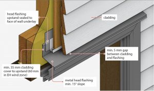
Figure 1
The flashing should be in a single piece that fully reaches both ends of the frame. Stop-ends must be formed at each end to prevent water running behind the cladding.
A 5mm minimum drainage and ventilation gap must be left between the top of the sloped flashing and the bottom of the cladding above it. This opening lets water drain from the assembly and allows air to enter to provide drying.
The head flashing upstand must be sealed to the face of the wall underlay with flexible flashing tape, or an extra layer of wall underlay must be dropped from above to create a gravity drainage path out over the flashing.
The total upstand must be 40mm minimum. The lap under the cladding must be a minimum 35mm (60mm in the extra-high wind zone).
The key requirements for head flashings are given in Acceptable Solution E2/AS1. This document also has other requirements in addition to those above:
- With direct-fixed claddings, there must be a 50mm sealant bead between the cladding and each end of the flashing.
- In cavity construction, there must be:
–– 10mm turn-ups acting as stop-ends, finishing at the inside face of the cladding and not passing through it.
–– ventilation of the cavity with use of a cavity base closure.
- In very-high and extra-high wind zones, there must be sealant between the underside of the head flashing and the top of the window head flange.
- Sloped heads must have specifically designed kickout flashings at the bottom edges of head flashings.
BRANZ research (Study Report 313) found that head flashings were more leak resistant when the upstand fitted tightly against the cavity closure. It also found that window head flashings handle run-off better where there is a greater clearance between cladding and flashing.
© BRANZ Builders Mate, Issue 75, December 2015
Register to earn LBP Points Sign in
3 Comments
Leave a Reply
You must be logged in to post a comment.


Silicone to head flashing end side
Silicone to head flashing end side
fine