Lightening the roof load
22 Jan 2019, Learn, Prove Your Know How
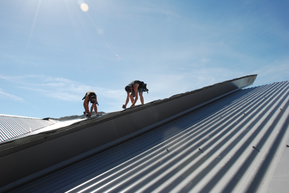
The replacement of a heavy concrete or masonry tile roof with a lightweight roofing material should be relatively straightforward, as the structure should easily support the lighter load. However, the roof’s resistance to wind uplift must also be addressed
When replacing a heavy roof with a lighter one, NZS 3604:2011 Timber-framed buildings outlines the necessary top plate connections.
Lighter roof must resist uplift
When wind passes over a roof, it affects the roof depending on:
- The wind direction relative to the ridge line (less critical for hipped roofs).
- Whether it is the windward or leeward side of the roof.
- The windward roof slope.
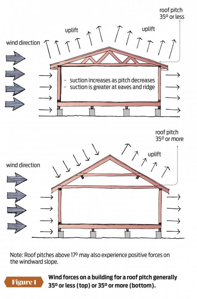
In general, wind parallel to a ridge creates suction or uplift across the roof area. When the wind is at right angles to the ridge:
- It always creates a suction or uplift on the leeward side of the ridge (Figure 1)
- On the windward side, the windflow creates:
- A suction or uplift for roof slopes up to 35°.
- A downward force on the roof for roof slopes over 35°.
- Uplift under some gust fluctuations when the roof slope is steeper than about 17°.
The uplift is created by the windflow reducing pressure across the roof area like the air movement over an aeroplane wing providing lift.
While the primary requirement for a heavyweight roof is to support the weight (downward load) of the roof, a lightweight roof must resist uplift.
Fixing top plates to resist uplift
Resistance to uplift is provided by the connection of the:
- Top plates supporting roof framing to wall studs
- Rafters/trusses to the top plate
- Purlins to rafter/top chord of truss.
Top plate connections are described in NZS 3604:2011 Timber-framed buildings paragraph 8.7.6 and Table 8.18. Table 8.18 sets out the top plate to stud fixing capacity requirements based on wind zone, the rafter or truss spacing of the roof and the loaded dimension of the wall. The table gives two fixing types:
- Type A – 0.7 kN fixing capacity, achieved by using two 90 × 3.15mm end nails
- Type B – 4.7 kN fixing capacity, achieved by using two 90 × 3.15mm end nails and two wire dogs.
Alternative fixing types that meet the fixing capacity requirements can be used.
Before a heavy roof is replaced, the fixing capacity requirements for a lightweight roof should be determined from Table 8.18.
Roof framing to top plate connections
Lintel resistance to uplift is described in NZS 3604:2011 paragraph 8.6.1.8 and Figure 8.12. Paragraph 8.6.1.8 requires that, where lintels are required to be secured against uplift as per Table 8.14, fixings should be as shown in Figure 8.12 and consist of 25 × 1mm straps with six 30 × 2.5mm nails at each end of the lintel to the adjacent trimming studs.
Trimming studs must similarly be fixed to the floor framing. An alternative 7.5 kN capacity fixing in tension along the line of the trimming stud is also permitted.
Providing additional fixing capacity
Having calculated the fixing capacity requirements against uplift, determining the existing fixing capacity may be difficult. There may also be practical issues with providing additional fixings as described in NZS 3604:2011, such as installing steel straps where external cladding is in place.
In these situations, add screw fixings into each stud adjacent to a rafter or truss through the top plate and into each trimming stud. The screw fixings should consist of two type 17, 100mm long, 14-gauge, self-drilling screws. Alternatively, proprietary stud to top plate fixings that comply with section 8 of NZS 3604:2011 are also available.
Purlin span, spacing and fixing
Older clay or concrete roofs may use 20 × 20mm battens over rafters spaced at around 400mm, while more recent tiles are installed over:
- 25 × 50mm battens at 450mm maximum span
- 40 × 50mm battens at 600mm maximum span
- 50 × 50mm battens at 900mm maximum span.
Long-run profiled metal roofing is typically installed over 70 × 45mm or 90 × 45mm purlins at 900–1200mm centres with a maximum span of 1200mm.
With the change from heavy tiles to light roofing, new battens will be required to match the new roof fixings. They need to match the fixing requirements for purlins given in NZS 3604:2011 and the roofing profile (corrugate, trapezoid) and thickness specified.
NZS 3604:2011 Tables 10.10 and 10.11 gives maximum purlin span, spacing and fixing distances to meet structural requirements.
Tables for purlins in E2/AS1 only cover purlin spacing based on the span of the roofing profile, which is determined by base metal thickness (BMT) and profile (Tables 11 and 12 for steel corrugate profiled roofing, Table 13 for trough profile and Tables 14 and 15 for trapezoid profile). The tables also cover the required fixing pattern for the wind zones.
Reproduced from Build 168 with permission from BRANZ
Register to earn LBP Points Sign in
2 Comments
Leave a Reply
You must be logged in to post a comment.


Wind factor
wind