Tackling tricky flashing
17 Jul 2018, LBP & Regulation, Prove Your Know How
One of the trickiest flashing details to design and construct correctly is a balustrade-to-wall junction flashing. This Codewords article gives a quick overview of this detail and provides some useful tips and other step-by-step information on how to correctly install this type of flashing
The junction where the capping of an enclosed balustrade meets the face of the main exterior wall of a building (typically at the end of a deck) is a high-risk location for weathertightness failure.
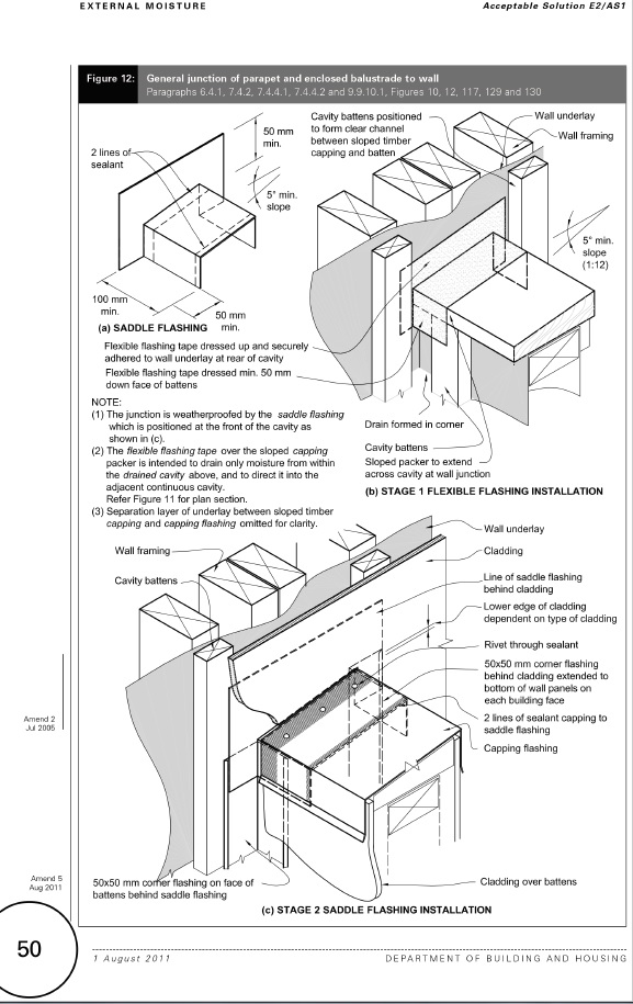
Where a metal cap flashing is used along the top of the balustrade, designs to Acceptable Solution E2/AS1 require fabricated metal saddle flashings to make these junctions weathertight.
However, the metal saddle flashings must be positioned correctly to ensure the junctions are weathertight.
Different saddle flashing at front of cavity
Figure 12 of E2/AS1 requires these saddle flashings to be positioned at the front of the cavity (immediately behind the outer cladding) – see NOTE (1) and detail (c) in the drawing. Placing these flashings at the front of the cavity reduces the likelihood of water entering the cavity where the flashing passes through it.
Importantly, this approach is different to most other cavity flashing details provided in E2/AS1. The narrow width of the balustrade means that only a very small volume of water could enter the cavity of the main wall above, so a different approach is acceptable. Any such water will instead run down to the flexible flashing tape where the sloped packer meets the main wall underlay, then be diverted to the adjacent cavity beside the balustrade, and eventually drain out its base.
Getting it right
E2/AS1 has specific requirements for parapets and enclosed balustrades:
- No penetrations are allowed in the top surfaces of parapets and enclosed balustrade walls. Where rails are required on balustrades, they must be side-fixed through the cladding into the framing as per E2/AS1 Figure 19 (on page 58 of the E2/AS1 document).
- The sides of cappings must overlap the cladding laps on both sides as per E2/AS1 Table 7 (on page 40) situation 2 or 3:
- 70mm plus kick-out (or bird’s beak for inside edge of enclosed balustrades as per E2/AS1 Figure 5 on page 38) for low, medium, high and very high wind zones
- 90mm plus kick-out or bird’s beak for extra high wind zone.
- All claddings on parapets and enclosed balustrades must be installed over drained cavities, except vertical corrugated steel
- In extra high wind zones, all claddings must be installed over a rigid wall underlay, consisting of minimum 7mm H3 treated plywood or 6mm fibre-cement sheet.
Refer to E2/AS1 for references.
More detail in flashings supplement
BRANZ has published step-by-step diagrams showing the installation sequence for the components to these junctions in their recent Build flashings supplement, which is available on the Build Magazine website.
As with the installation of any flashing, sequencing of installation steps is key to a good outcome. The balustrade-to-wall junction can be found in section 4.5 of BRANZ’s ‘Build flashings supplement’. This key resource provides a comprehensive overview of construction sequencing for most common residential flashing applications, and explains the installation process.
This article first appeared in Codewords – Issue 84
Register to earn LBP Points Sign in
3 Comments
Leave a Reply
You must be logged in to post a comment.

degrees
Good to get flashings right
tricky